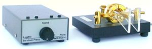
I do factory authorized repair on the Logikit CMOS-4 Keyer. This service is available for factory assembled and kit built units. Please contact me via Email for rates and shipping instructions.
- If you need replacement parts for any of the Ham Supply products or repair of products other than the CMOS-4 and SCAF-1 please contact them at https://www.hamsupply.com/contact/
Negative keyed rigs
Some of the older negative keyed rigs may not key properly with the CMOS-4. If you have this problem try putting a 680 ohm resistor in parallel with R9 and a 470 ohm resistor in parallel with R20. The disadvantage of this change is an increase in power supply current which may be an issue if running on battery power.
CMOS 4 Service Bulletin #2
Service Bulletin #2 is now available for the CMOS-4 keyer. Click on the link to view it.
CMOS 4 Service Bulletin #3
Service Bulletin #3 is now available for the CMOS-4 keyer. Click on the link to view it. If you would like Service Bulletin #3 installed in your keyer contact me via Email for rates and shipping instructions.
Ron, K0QVF
RFI notes:
If you think you have an RFI problem with the keyer here are some things to try:
- Keep all external wires as short as possible.
- Use shielded wire for all external wires.
- In extreme cases add a 0.1 or 0.01 uf capacitor to ground on each of the external connections.
Power supply notes:
If you are using an external power supply there can be an initialization problem if the voltage ramps up at to slow a rate. This problem can be avoided if batteries are always installed in the keyer. There will be no power consumed from the batteries as long as there is external power applied.
If you are using batteries for power the battery voltage must be at least 4.0 volts.
The voltage on pin 40 of U2 should be approximately 4.7 if external power is being used and 4.25 if fresh batteries are the power source.
If your keyer does not work properly after assembly it may be helpful to have someone else check your work. If all parts and connections look OK remove the chips from their sockets and go over the solder joints on the circuit card with your soldering iron. Sometimes a connection may look good but may be open.
If your keyer does not initialize properly try holding one end of a wire on ground and touch the other end to pin 1 on U2.
If you experience a lock-up and the hard reset listed above does not recover operation try removing all power for a number of hours. In some cases the residual charge takes some time to bleed off due to the very low power consumption of the keyer components.
Here are some resistance checks that you can make. All readings should be within + or – 5% of the listed value. When doing these tests both chips should be removed from their sockets.
Reference the following to pin 40 on U2.
| Pin | Resistance |
|---|---|
| U2-1 | 15 k |
| U2-2 | 330 k |
| U2-3 | Zero |
| U2-4 | 330 k |
Reference the following to pin 2 on U2.
| Pin | Resistance |
|---|---|
| U2-4 | Zero |
| U2-10 | 15 k |
| U2-11 | 15 k |
| U2-12 | 15 k |
| U2-13 | 15 k |
| U2-14 | 15 k |
| U2-15 | 15 k |
| U2-16 | 15 k |
| U2-17 | 15 k |
Reference the following to power ground.
| Pin | Resistance |
|---|---|
| U2-6 | Open |
| U2-7 | Open |
| U2-8 | Open |
| U2-20 | Zero |
| U2-29 thru 34 | Zero |
| U2-36 | Zero |
| U2-37 | Zero |
| U2-38 | Open |
| U2-39 | Open |
| U2-1 | Zero |
| U2-2 | Zero |
| U2-3 | Zero |
| U2-4 | Zero |
| U2-7 | Zero |
This page last revised on January 20, 2018